GRSplits
A Circuit Plot Utility for SPLITS
GRSplits is a graphics input/output processor designed to visualize the circuit model represented by a SPLITS or FCDIST computation module input file. This program greatly simplifies the task of manipulating, visualizing and checking the components of a SPLITS or FCDIST circuit.
Technical Features
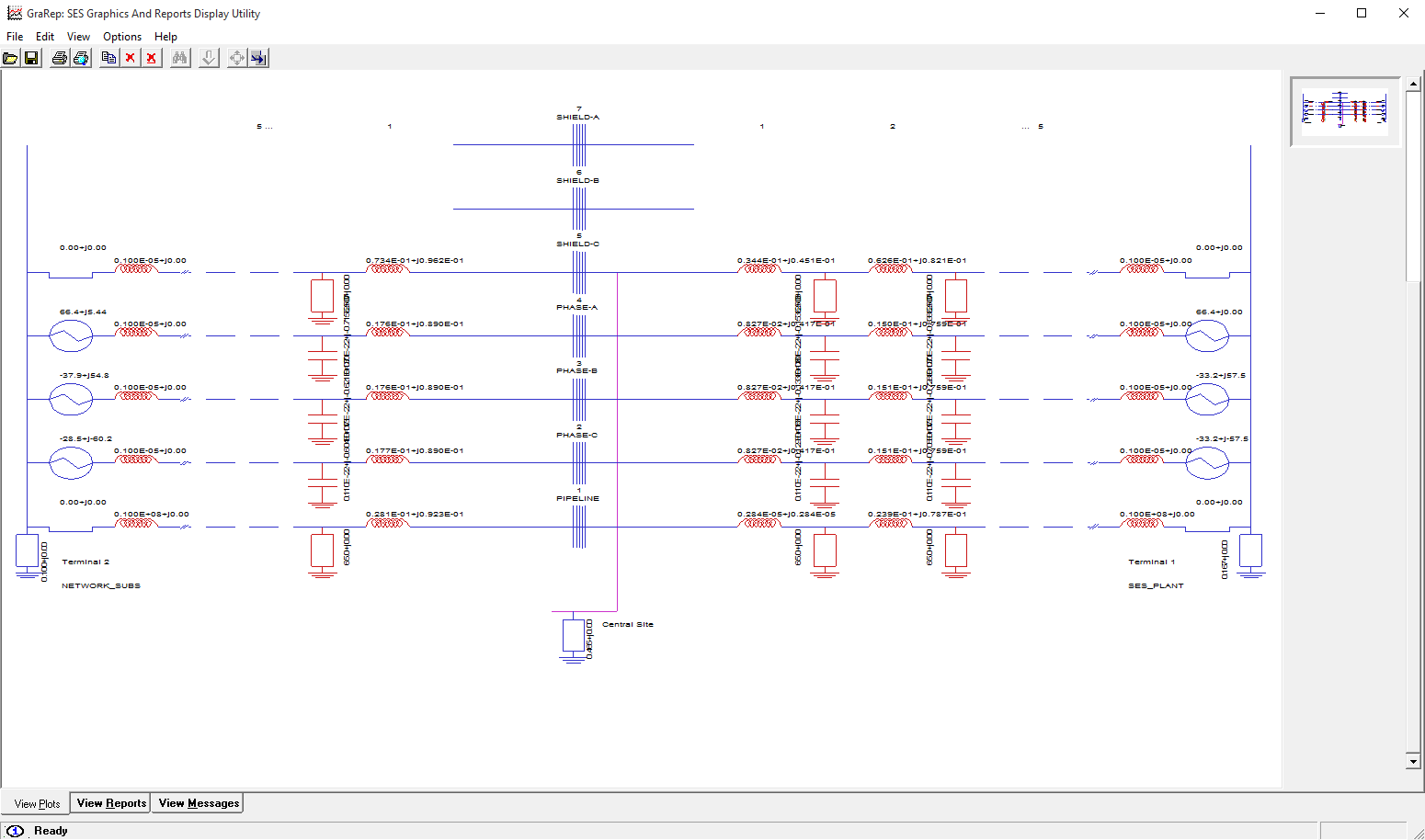
The entire circuit or only the parts of interest can be plotted. This means that it is possible to plot only the central site or one or more terminals or some specified sections (spans) for a given terminal. Up to four terminals can be displayed simultaneously. The numerical values of the longitudinal and shunt impedances can be printed for each section.
The interconnections between the various phases of a given section are also displayed when their impedance is below a specified threshold value. Identical sections are replaced by a single section, followed by dashed lines, if desired. Computation results, such as shunt voltages and series or shunt currents can be displayed at the Central Station, at Terminals and for a range of sections as required. Plots can be produced in most popular formats.
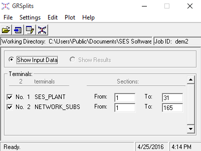
The program analyzes the contents of the input file and displays the results in the Terminals frame. The user may select which terminals and sections to display. The Plot Style and the text display ( Show Text ) options can be set accordingly. If desired, the graphical settings can be adjusted by selecting Set Graphical Factors in the Settings menu and the display of interconnections can be turned on or off by choosing an appropriate Interconnection Threshold . Once all the options are configured, the circuit plot can be produced by selecting Plot Circuit in the Plot menu. The following is a short description of the most interesting options available in the program.
Plot Style Options: This option selects which parts of the circuit are to be displayed. Five options are available: All, Central Site and Terminals Only , Central Site Only, Sections Only and Terminals Only .
Show Text Options: Selects what kind of circuit data are to be displayed on the plot. Up to five types of data can be simultaneously displayed. Line Impedances, Shunt impedances, Source Voltages, Connection Impedances and Bus Name .
Terminals: Defines which terminals and sections will be displayed. Any combination of up to four terminals can be selected.
Interconnection Threshold : This option on the program's main screen is used to control which mutual connection impedances between the lines of the circuit (interconnections) are shown. The connection impedances below this threshold will be indicated by a line connecting the corresponding wires.
Graphical Settings : The Graphical Settings dialog, which can be accessed from the Set Graphical Factors item from the Settings menu, can be used to control the appearance of the generated plot. The following options are available: Color, Output Device, Character Height and Rescaling Factor .
Input File Editor : This item which is invoked by selecting the Edit Input Data File item under the Edit menu on the program's main screen, can be used to view or modify the currently loaded input file. The editing capabilities of that window are those of a standard text editor, and are available through the usual keyboard shortcuts.
For an interactive 3D display of the circuit, use the GrSPLITS-3D software utility.


