AutoGroundDesign
The AutoGroundDesign package performs automated analyses of grounding (earthing) systems of any arbitrary perimeter and identifies an economical grid configuration complying with user defined safety criteria that can be used as the design for grounding grids that are electrically small enough to be considered equipotential.
Technical Description
The only fully automated software tool capable of analyzing and designing grounding systems with no user intervention between design phases, AutoGroundDesign’s powerful and intelligent functions help electrical engineers to safely and efficiently design horizontal, arbitrarily shaped grounding installations.
A multiple-step approach is used for the system design, beginning with the manual specification of parameters related to the grounding system, soil and fault current data, and safety criteria. Then the automated design process begins, starting with a grid consisting of a buried metallic plate (which provides the lowest resistance, touch and step voltages) to determine if required safety limits are achievable. If yes, a grounding system consisting of a minimum number of conductors is computed. From these results, a preliminary design is then selected based on the SES reference database, other intelligent rules, or as specified manually by the user. Next, the initial design is refined recursively using rule-based techniques and algorithms to improve its performance and to satisfy safety constraints, while reducing the overall cost of the grid. These steps are described in greater detail below.
Extensive collections of pre-defined grids have been analyzed and constructed. A strategy has been devised to quickly identify an appropriate grid, while at the same time minimizing the size of the database. The time devoted to designing a safe and cost-effective grounding grid is minimized by the use of these automation techniques and appropriate databases.

The component-based nature of the software package allows you to focus on your immediate needs, which may initially be, for example, to compute the resistance of a simple grid. Then as your needs evolve, for example to performing complete safety analyses of complex grounding systems of substations, you can consider upgrading to a software package with more sophisticated capabilities.
Two AutoGroundDesign packages are available:
This package can be used to analyze any horizontal arbitrarily shaped grounding system, and it can model soil structures comprised of two horizontal layers. It computes the grounding system resistance and potential rise, as well as the earth potentials throughout the region around the grounding system. It also allows you to carry out a full safety analysis of the touch and step voltages at any location inside or outside the grid. This package also includes a powerful module which computes the distribution of fault current between the grounding system and other metallic paths such as: overhead ground wires, shield wires, neutral conductors, and cable sheaths or armours. The package also comes with a resistivity measurement analysis module that converts measured data into a suitable soil model.
This package includes everything in the above package, and adds the ability to model soil structures comprised of any number of horizontal soil layers (multilayer soils).
Both packages include utilities (e.g., a conductor ampacity computation module (SESAmpacity), graphic servers, text editors, etc.).
Background
A grounding system design requires several iterations before obtaining a safe configuration. Therefore, it can be quite time consuming. It is difficult to account for the large number of variables e.g., topology and dimensions of the grounding system, burial depth, type and characteristics of the soil structure and material used for the grid’s conductors (horizontal wires and grounding rods, etc.) that can affect the grounding system performance. The AutoGroundDesign software package offers powerful and intelligent functions that help electrical engineers design safe grounding systems quickly and efficiently without the intervention of the user between various phases of the design. AutoGroundDesign takes into account the full complexity of the system with strategies and techniques that have been developed to allow the automated design to be applied to horizontal arbitrarily shaped grounding systems.
This is the ideal tool to examine, enhance and optimize a large number of existing substations that require updates due to increased fault levels or new safety standard requirements. It can also be used as the first step in a more complex design cycle requiring manual interventions.
This is the ideal tool to examine, enhance and optimize a large number of existing substations that require updates due to increased fault levels or new safety standard requirements. It can also be used as the first step in a more complex design cycle requiring manual interventions.
Features
AutoGroundDesign has the following unique features. It:
Grounding System Design Technologies and Procedures
Consider the traditional process of designing a substation grounding system. Based on experience and on the substation ground bonding requirements, a preliminary grounding system configuration is developed and analyzed. The calculated results are examined to determine if all design requirements are met. If not all design requirements are satisfied, or if they are exceeded by a considerable margin thereby suggesting the possibility of significant savings, design modifications are made to the grounding system and the design analysis is started again.
To produce an optimized design, knowledge of the soil structure and the actual fault current flowing into the substation is required. Also, a large number of factors such as the geometrical proportions of the grid, its depth, the type of grid conductors and whether grounding rods are attached to the grid are essential.
A multiple-step approach is used for the automated grounding system design.
Automated Grounding System Design Structure
The automated grounding system design software integrates the following modules and has the structure shown below:
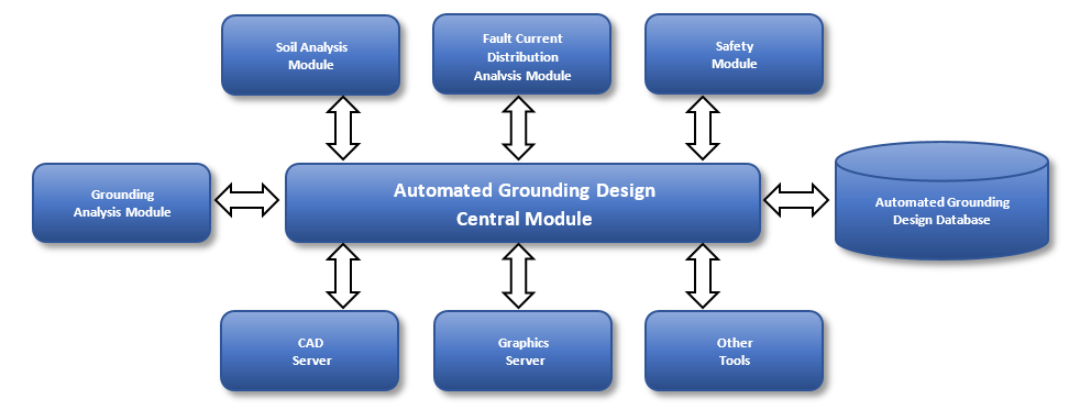
This core and controlling module has a simple interface that allows users to establish an automated grounding system design quickly and efficiently. This module manages and coordinates input data and is used to calibrate the iterative process for automatically designing a grounding grid, with the ultimate objective of providing a design that meets all requirements and yet is not overly conservative, and therefore cost-effective. The design parameters include the selection of the methodology to obtain the initial design of the grounding system, to specify which grid database methodology is to be used for the automated design, to specify the maximum number of design iterations, and the rate at which the design of the grid evolves with every iteration.
Grounding Analysis ModuleThis module is used to analyze power system ground networks subjected to AC or DC power frequency currents discharged into various soil structures. It computes the safety performance of the grounding grid, in terms of GPR, touch and step voltages.
Soil Analysis ModuleThis module is dedicated to the development of equivalent earth structure models based on measured apparent resistance or resistivity. It can generate models with horizontal multilayer soils.
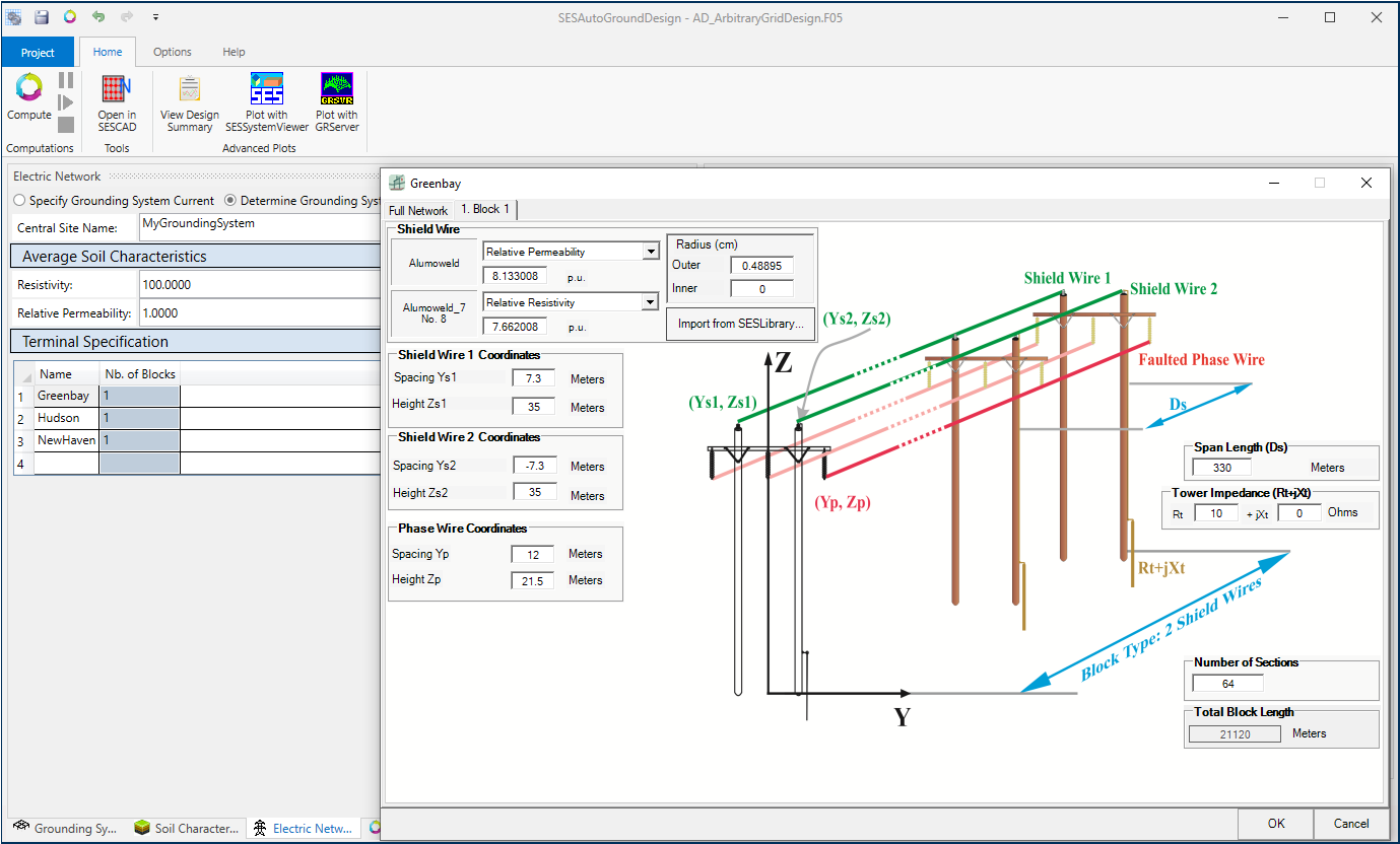
Fault Current Distribution Analysis ModuleThis module calculates the fault current distribution in multiple terminals, transmission lines and distribution feeders using minimal information and a simple set of data concerning the network. Terminals with multiple blocks can be defined, where each block can have different line parameters, and other characteristics such as span length values and the positions of neutral and phase conductors can likewise vary from one block to the next. It provides the actual fault current flowing into a grounding grid, as well as currents in the shield wires, tower structures and cable sheaths. Self and mutual impedances of the shield wires and cable sheaths are also computed and available.
Safety ModuleThis module generates safety threshold values based on IEEE Standard 80, IEC Standard 479, the user’s own standard, or a combination of these for two geometrical zones (inside and outside the grid), representing areas with typically different safety thresholds. The computed safety voltage limits are used to decide whether to stop or continue the design process. The parameters to determine the safety voltage limits are: fault clearing time, earth surface covering layer (e.g., crushed rock) resistivity and thickness, equivalent subsurface layer resistivity (this is the resistivity of the soil beneath the layer that covers the surface of the earth), body resistance, optionally specified foot resistance and resistance of protective wear such as gloves or boots, and a fibrillation current threshold computation method.
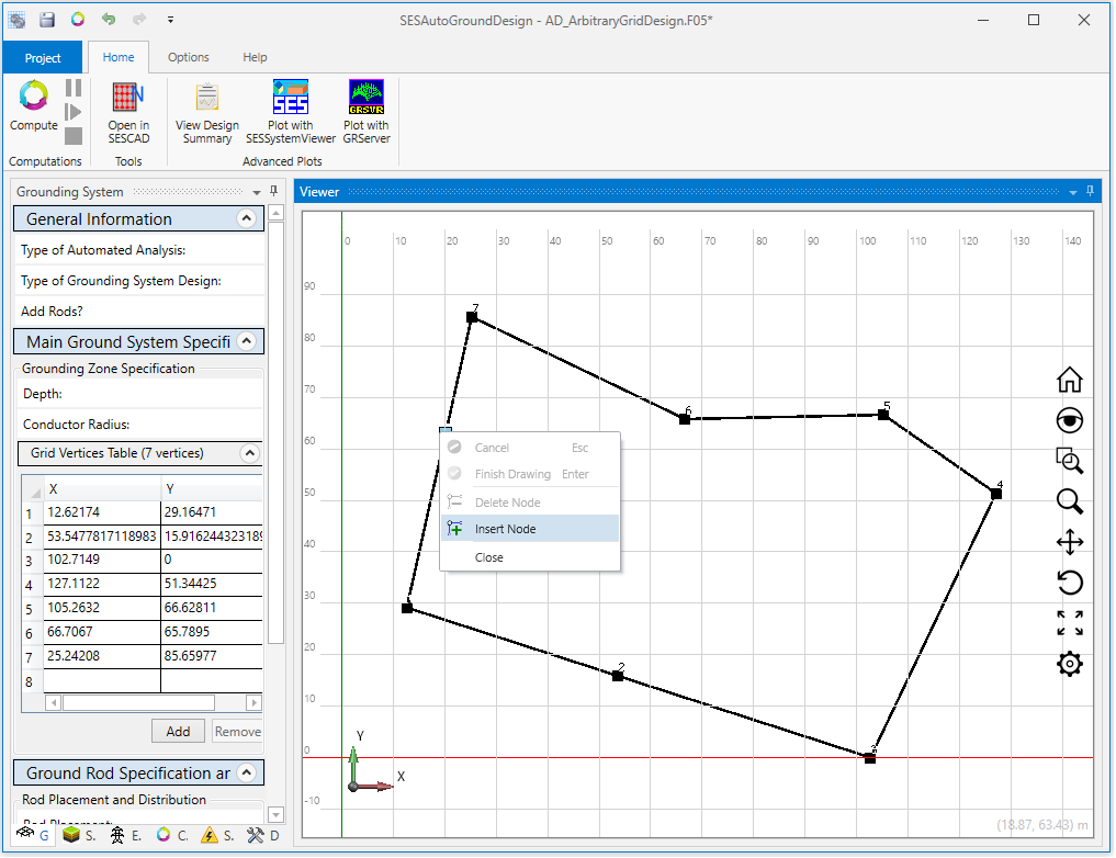
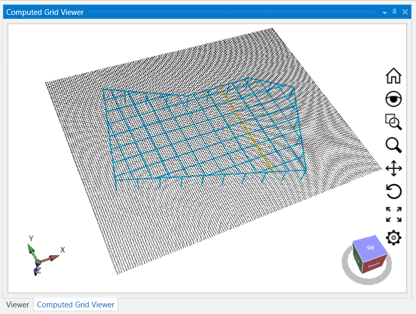
View, Plot and Report ToolsA CAD-based module is used to view or edit (editing requires an AutoGrid Pro or AutoGround/MultiGround software package) three-dimensional grounding grids consisting of straight-line segments. The line segments represent either metallic conductors or observation profiles. They can be viewed from any direction, in a variety of ways in SESCAD. AutogroundDesign also features an embedded 3D viewer to view the resulting grid.
In addition, computational results as printed in the output file can be viewed and plotted via the View Design Summary button, and plots and reports of the computation results can be viewed by launching SESSystemViewer or GRServer using the corresponding buttons.

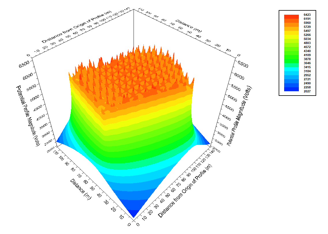
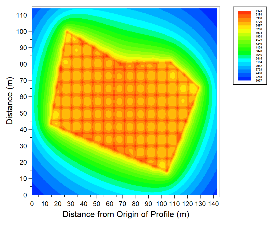
GRServer serves as a powerful output processor to display the computation results in various graphical or print formats. This module also has the capability to view the input data and even launch the grounding analysis module.
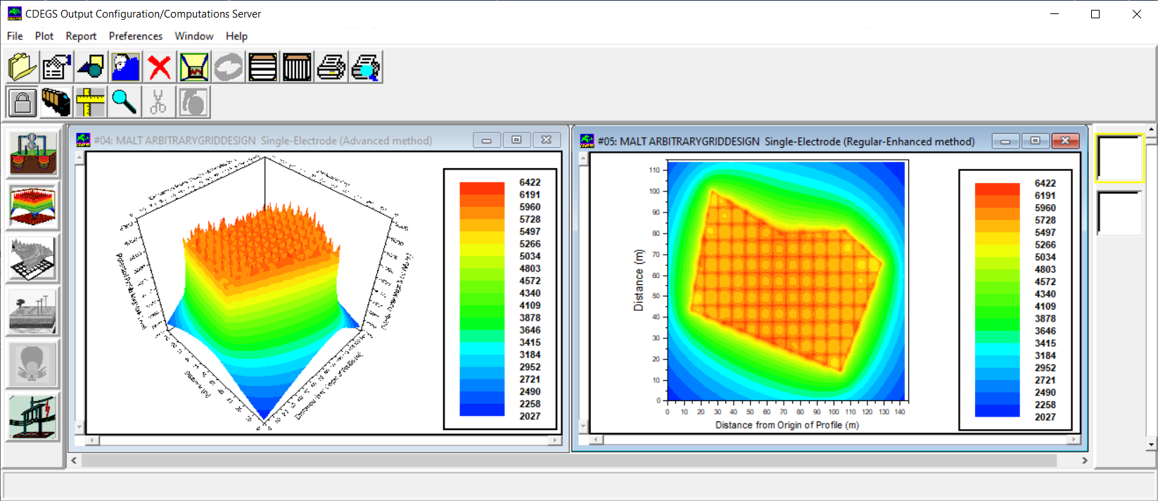
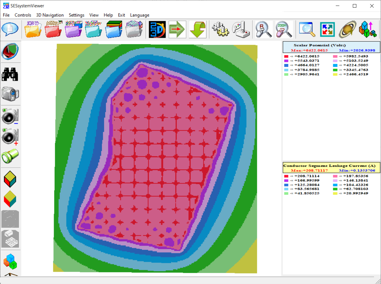
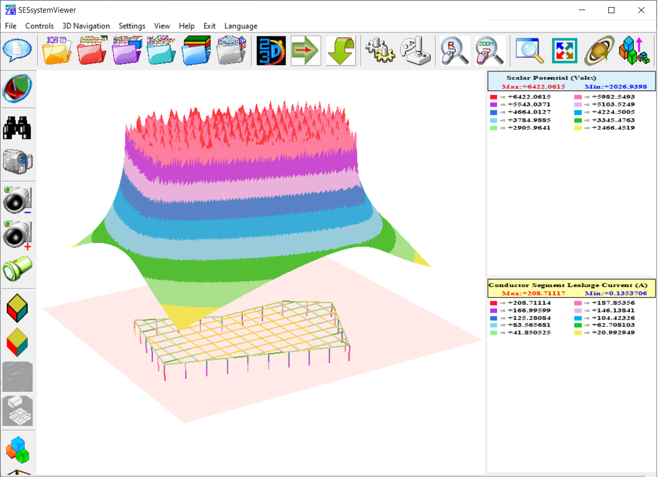
Lastly, SESSystemViewer displays 2D or 3D computation results directly over the grounding grid system configuration.