Right-of-Way Pro
A powerful software package for the analysis of electromagnetic interference between electric power lines and exposed utilities and adjacent installations.
Computation Modules Included Software PackagesSESEnviroPlus SESTLC Pro CorrCAD SESShield-2D
Technical Description
Right-of-Way Pro is a powerful automated AC Interference analysis software package that accurately computes voltages and currents imposed on exposed metallic utilities by electric power lines, power cables and electrified railways by inductive, capacitive and through-earth conductive coupling. Exposed utilities such as pipelines, railways, communication lines and other exposed structures, whether buried or aboveground, are often vulnerable to large steady-state or fault currents on the electric lines. The Right-of-Way Pro software package consists of a powerful set of integrated engineering software modules designed to accurately analyze these interference problems and provide mitigation with a global perspective, starting literally from the ground up.
Capabilities
Right-of-Way Pro models complex arrangements of buried and aboveground conductors and computes currents and voltages resulting on every exposed utility modeled, including conductors associated with the power line, for normal load and fault conditions. It models simple and multi-component conductors, including bare or coated pipes, rail tracks and pipe-enclosed cable systems buried in soil. Right-of-Way Pro, coupled with toll-free support from the world's leading R&D design team in this specialty, provides you with an array of cost-effective solutions for problems ranging from simple interference analyses to the behavior of complex networks of aboveground and buried conductors energized by steady state and fault currents as well as by lightning strikes. The integrated CAD graphical interface, ROWCAD, allows you to define the geometry of the paths part of a Right-of-Way Pro in a graphical environment. ROWCAD automatically defines the section cuts on each path so that the interactions between them are computed as accurately as possible. Flexible data reporting and graphing utilities allow you to collect and illustrate any aspect of the results that are important for your work.
Right-of-Way Pro provides a complete interference analysis and mitigation design tool based on the computation modules of the CDEGS software package modules such as RESAP for soil resistivity analysis, TRALIN for line parameters calculation, SPLITS for solving electrical circuits and MALZ for the frequency domain grounding analysis. SPLITS is essentially an electrical circuit analysis program capable of solving a variety of commonly encountered electrical problems through accurate simulation of the electric network to be studied. MALZ models grounding systems including mitigation grounds and gradient control wires and computes through-earth coupling between faulted power line structures and nearby utilities while accurately accounting for the EMF interference component.
Detailed Description
This powerful integrated software package analyses the electromagnetic interference between electric power lines and adjacent installations such as pipelines, railways and communication lines. It is especially designed to simplify and automate the modeling of complex right-of-way configurations. Right-of-Way Pro can automatically compute the interference level during steady state conditions accounting for both the inductive and conductive coupling while taking into account variations in the characteristics of the soil along the right-of-way corridor. Furthermore, it can automatically create phase-to-ground faults along any transmission line at regular intervals throughout the right-of-way corridor, as specified by the user. This automation process yields the maximum envelope (curve of the maxima) of quantities such as pipeline GPR (i.e., ground potential rise), pipeline longitudinal and leakage currents, rail GPR or rail to rail voltages, tower potentials and earth injection currents, etc., along the right-of-way.
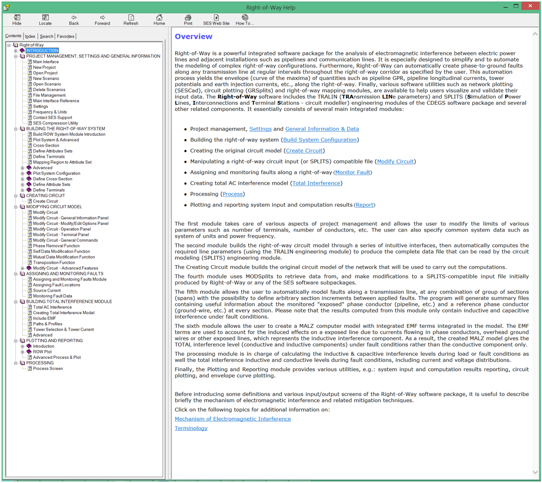
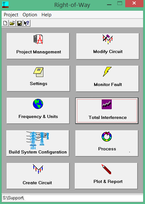
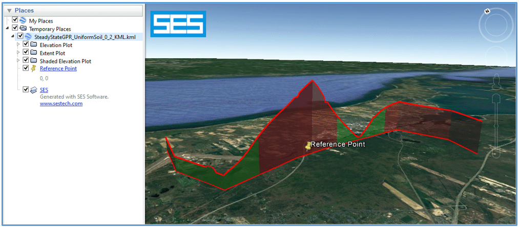
You can start your project with data based on the Keyhole Markup Language (KML), which is an XML notation for expressing geographic annotation and visualization within Internet-based, two-dimensional maps and three-dimensional Earth browsers such as Google Earth™ KML files, and use the Universal Transverse Mercator (UTM) projection with the World Geodetic System datum surface (an oblate spheroid) to convert the curved system into 2-D coordinates compatible with SES Software. Various software utilities, such as circuit plotting and right-of-way mapping modules are available to help you visualize and validate your system and related computation results. A KML plot type can be specified to create a Google Earth™ file that displays path coordinates in combination with computation results directly on the Google Earth™ world map. The Right-of-Way Pro user interface essentially consists of several main integrated modules:
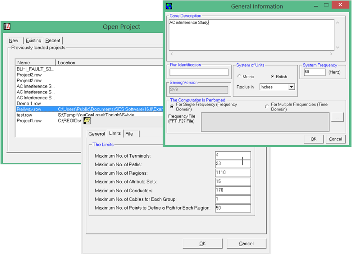
The first module takes care of various aspects of project management and allows you to modify the limits of various parameters such as the number of terminals and conductors, etc. You can also specify common system data such as the system of units, whether the study is to be carried out in single frequency domain mode (specify a power frequency) or in transient mode requiring multiple frequency specifications derived from the SESFFT computation module.
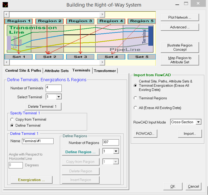
The second module builds the right-of-way circuit model through a series of intuitive window interfaces that can import the network data built from ROWCAD, then automatically computes the required line parameters to produce the complete circuit input data file that is then ready to be energized, either by normal load currents or fault currents.

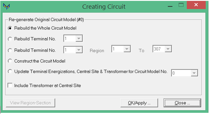
The Create Circuit module computes the line parameters and builds the original circuit model of the network that will be used to carry out the computations.
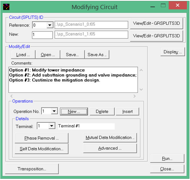
The fourth module (Modify Circuit) uses a specialized tool (ModSPLITS) to retrieve data from— and make modifications to—a SPLITS-compatible input file that was initially produced by Right-of-Way Pro or any other SES application.
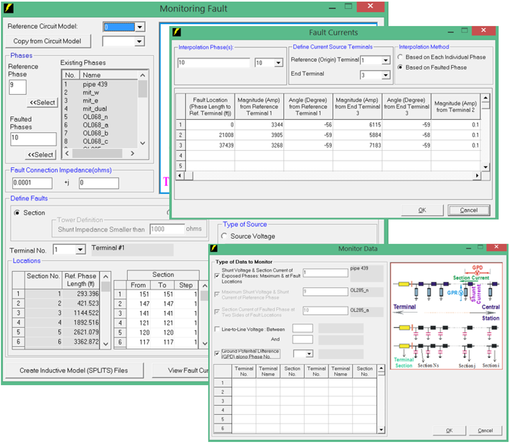
The fifth module (Monitor Fault) allows the user to automatically model faults along a transmission line, at any combination of groups of sections (spans), with the possibility of defining arbitrary section increments between applied faults. The program will generate summary files containing useful information about the monitored exposed phase conductor (pipeline, railways etc.) or any line conductors, and a reference phase conductor (ground-wire, etc.) at every span (section) of the circuit.
The sixth module (Total Interference) allows a user to automatically create a MALZ computer model of the grounding systems (including tower structure grounds) and mitigation wires along the target right-of-way that may have an influence on the conductive interference with the full EMF (induction) components integrated into the model. The EMF components are used to account for the induced effects on an exposed line due to currents flowing in phase conductors, overhead ground wires or other exposed lines. They represent the inductive interference that was calculated by the circuit model computation engine. As a result, the MALZ grounding analysis computation module gives the total interference level (conductive and inductive components) under fault conditions rather than the conductive component only.

The Process module calculates the inductive & capacitive interference levels during load or fault conditions, as well as the total interference inductive and conductive levels during fault conditions, including current and voltage distributions.

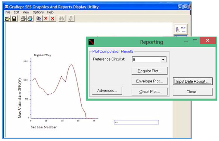
Finally, the Plot & Report module provides various utilities, e.g., system input & computation results reporting, circuit plotting and envelope curve plotting.
Right-of-Way Pro
- Accommodates any arrangement of multi-phase conductors: pipe-enclosed cables, pipelines, solid, hollow, stranded and composite conductors, insulated and bare conductors, overhead and buried conductors, and irregular phase configurations. Cable conductors can have a core, sheath, armor, and arbitrary insulations.
- Analyzes complex, multi-phase, multi-winding transformers located anywhere along the electric network in full detail. Built-in single-phase and 3-phase multi-winding transformer models, including autotransformers, are also available.
- For overhead conductor arrangements with little regularity, conductors can be specified one at a time and may be completely different from one another. For systems which include buried conductors such as pipelines and pipe-enclosed cables, conductors are specified individually or as a group.
-
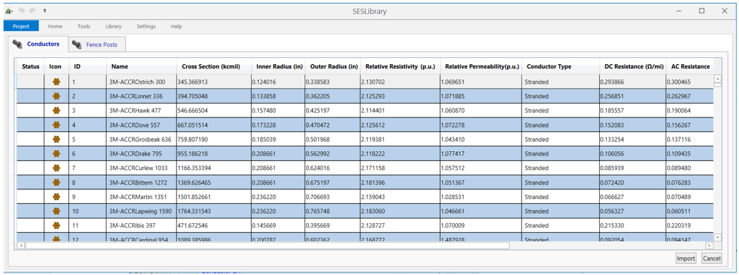
An extensive conductor database is available to facilitate input operations. You can add your own products to the databases at any time.
- Analyzes electromagnetic interference effects, currents and voltages in every span of a multi-conductor, multi-phase power network and in neighboring victim circuits sharing the same corridor. Ground impedances or interconnections to other conductors can be specified for any number of conductors at any number of locations. Key screens provide illustrations clearly representing the data to be entered and extensive on-line context-sensitive help is one keystroke or mouse click away.
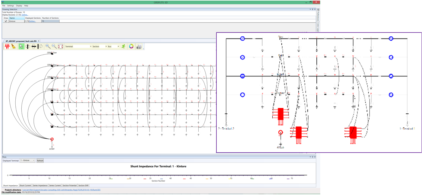
- Plots the leakage current, longitudinal current, ground potential rise (GPR) and arcing distance throughout your conductor network, directly on a schematic diagram of the network. For fault current distribution analyses or right-of-way simulations, plot multiphase networks, transmission line impedances, voltages, and currents as a function of distance or span number. Spreadsheet functions facilitate and enable rapid data entry. An input/output processor GrSplits-3D is available to view the circuit model represented by a Right-of-Way Pro or SPLITS input file. This tool greatly simplifies the task of manipulating, viewing and checking the components of the specified circuit. The most salient features of this utility are as follows.
Finally, when you need an explanation or a rapid reminder of what any portion of a screen is for, simply click on that part of the screen and press the F1 function key; a context-sensitive help screen will appear instantly. If you are unable to find answers to your questions in either the help file or the manuals, SES experts are just one toll-free phone call away or, if you prefer, you may send your inquiries to us via email and you will promptly receive a thorough reply.