Right-of-Way Pro/RowCAD
RowCAD development has made substantial gains in achieving its ultimate goal: a single and modern user interface to perform all specification, computation, and results reporting actions in performing an AC interference study.
Modify Circuit operations can be defined directly in RowCAD. Self Data Modification, Phase Removal and Mutual Data Modification operations can be specified.
The Monitor Fault module in RowCAD, introduced last year, now includes all functionalities available in ROW. It also now includes processing options such as creating files only, creating and running files, and parallel computing.
RowCAD has an interface to specify the key parameters of the Total Interference computation parameters. Since the advent of the multi-region soil model in MALZ, the Total Interference parameters specification is not only simpler, but the computations are now much faster under steady state conditions, and rely far less on ad hoc corrections, thereby enhancing accuracy. The Total Interference interface also includes processing options such as creating files only, creating and running files, and parallel computing.
RowCAD allows running SPLITS fault circuits in Monitor Fault, and MALZ models in Total Interference, on parallel CPU cores, with a user-specified Number of Parallel Runs.
The Computation Trace panel, which so far used to display the progress of the Generate Regions and Create Circuit processes, now reports on the progress of the Monitor Fault and Total Interference processes.
A number of other improvements were made such as ROW’s Plot & Report which now allows users to specify whether they want to use Reach Touch Voltage or Touch Voltage in reporting Total Interference results. RowCAD now supports the 64-bit architecture. The TRASPL folder can be omitted from Save Scenario As and archiving scenarios to save space. The performance in editing large polyline coordinates grid has been greatly improved. Improved warning messages about possibly overwriting files in the course of computations have been added, and RowCAD’s help files were updated to reflect all improvements.
See the article entitled"Improvements in RowCAD and Right-of-Way Pro" in the 2023 Users' Group Conference Proceedings for further details.
SESTLC
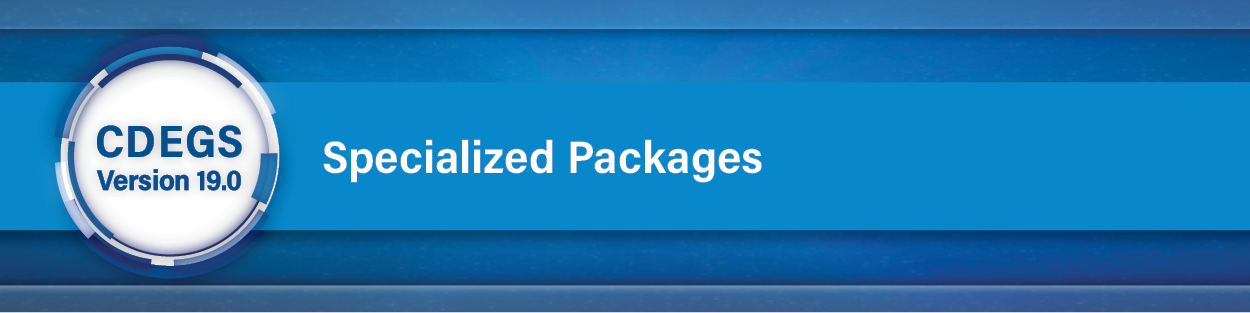
A new feature to include the capacitive coupling in the interference from transmission lines following a jagged path to a nearby above ground exposed line is implemented in SESTLC. This is an enhancement to the previous modelling of transmission lines following a jagged path in Steady State Interference or in Fault Condition Interference studies in SESTLC developed by SES in 2019. The capacitive coupling can be an important part in interference when both the transmission lines and the exposed line are in the air.
See the article entitled “Contribution of Capacitive Coupling in Interference from Jagged Transmission Lines in SESTLC” in the 2023 Users' Group Conference Proceedings for further details.
CorrCAD, SESCurvefitDigitizer and SESCPCalculator
These three corrosion programs have been upgraded to a 64-bit platform, allowing larger cases to process faster and run without problems due to memory limitations.
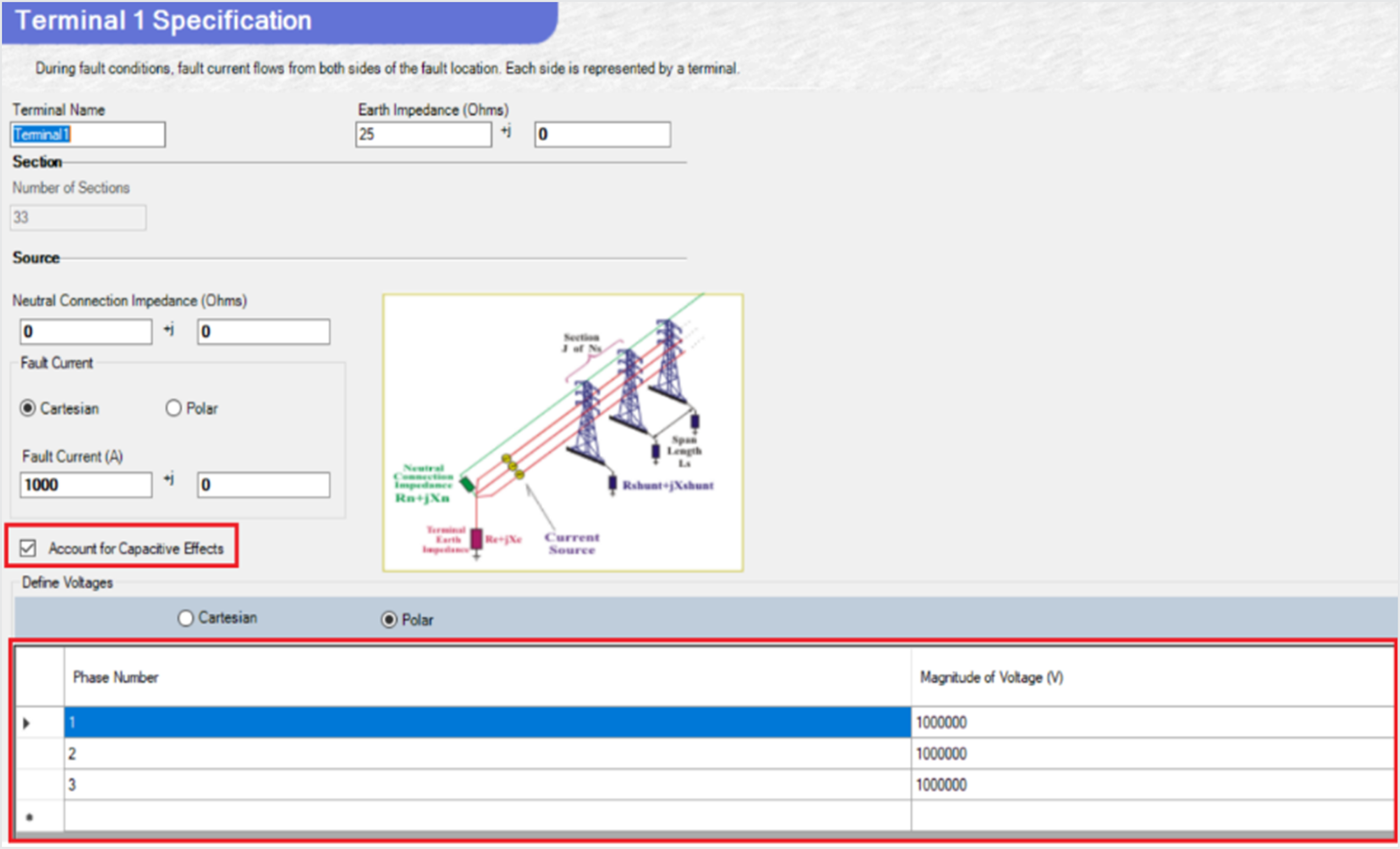
Native Potential Database: The new Native Potential database contains complete materials electrochemical potential series, derived from various references. In addition to the existing Native Potential for popular metals directly available in CorrCAD and SESCPCalculator, the native potential data can now be imported seamlessly from SESLibrary as shown in the screen below (see the article “SESLibrary New Databases and Features”).
Electric Field Display: Once the computation is completed, this new version of CorrCAD can report and display the “Electric Field”, which is one of the design criterions required by various corrosion international standards.
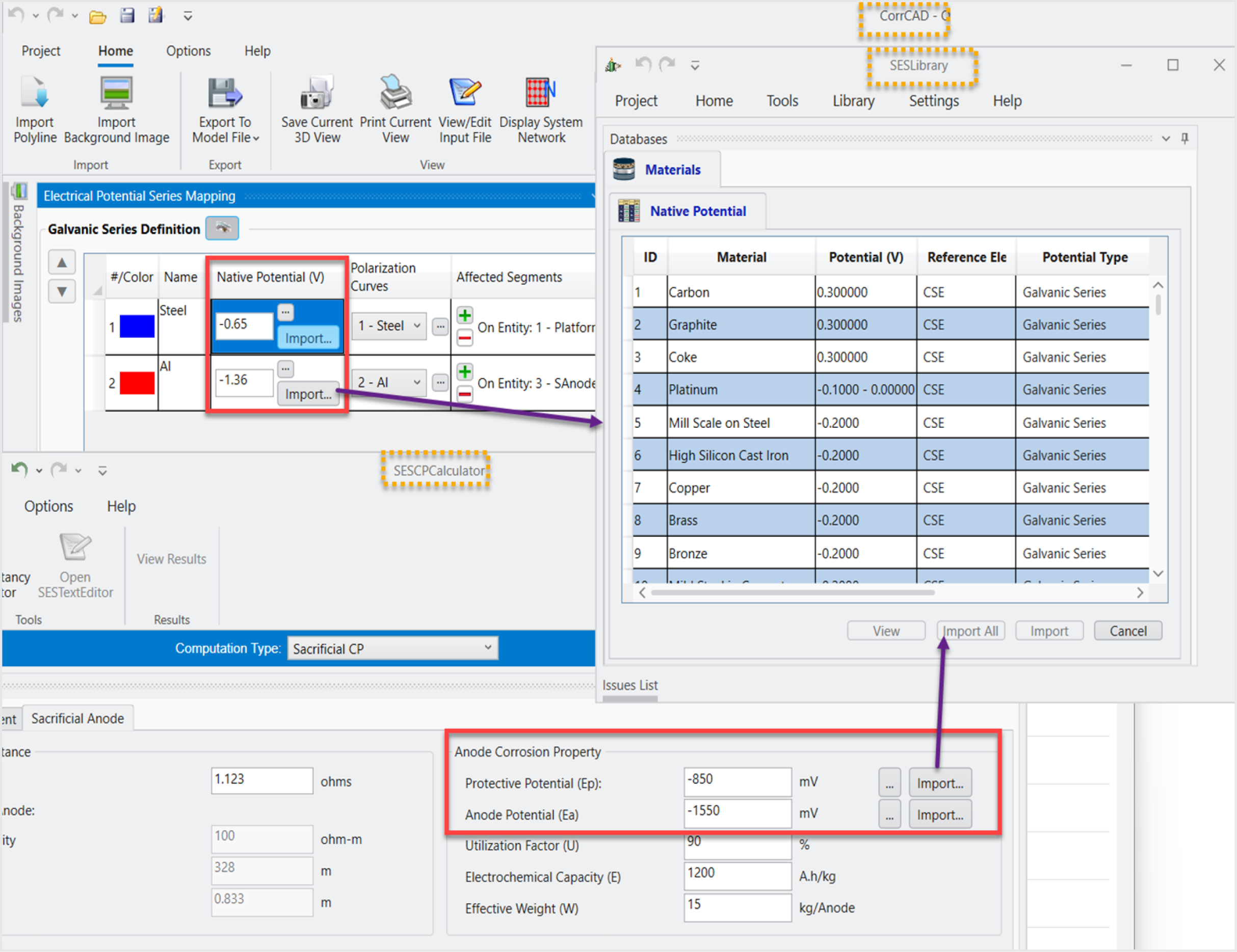
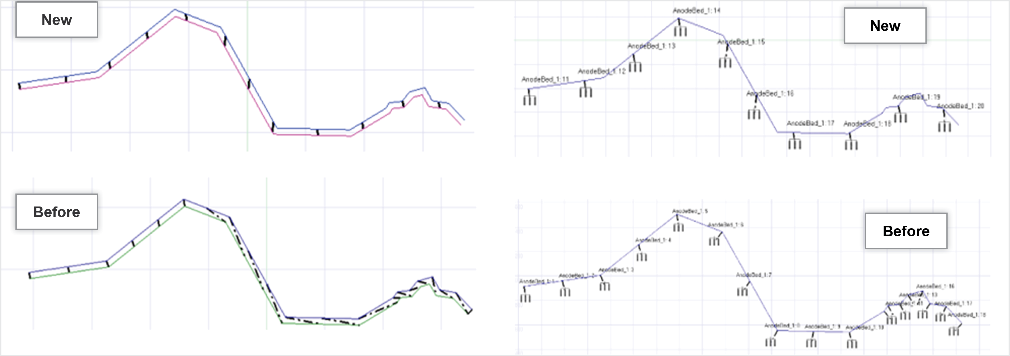
Enhanced Polyline Operations and Rendering: In the "Polyline Operation Tool" of CorrCAD, the polyline shift operation algorithms have been considerably improved as shown below.
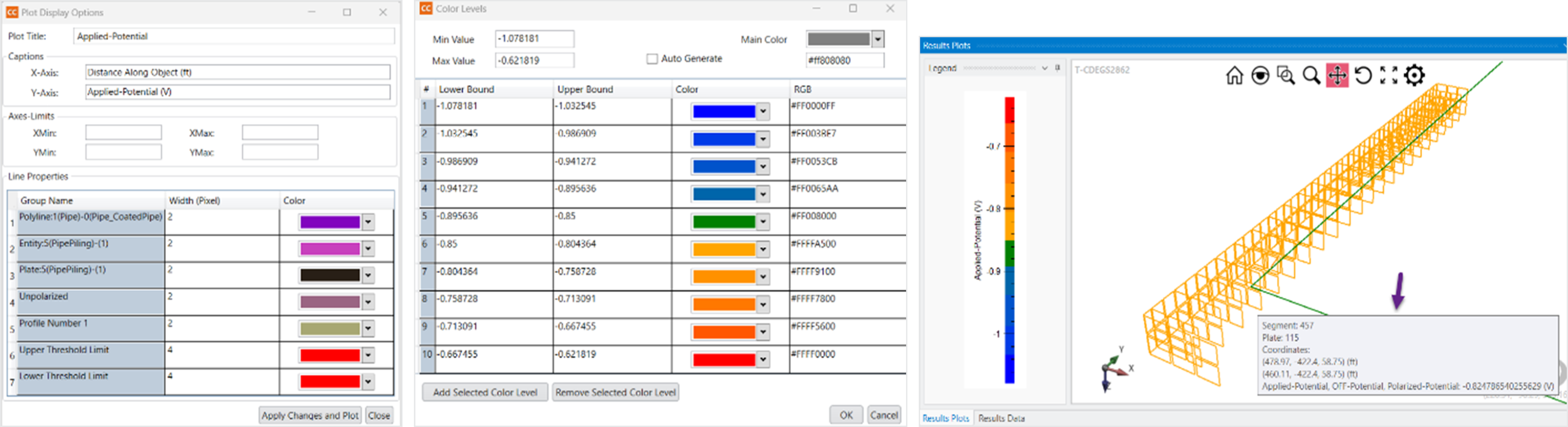
The new plot module of CorrCAD provides different Rendering options where the content depends on the selections made in the Chart Type and where you can tune the appearance of different graphical objects like labels, axis formatting, 2D-Spot colors level, etc. Furthermore, in the 3D plot, the conductor information, including its properties and computation results of the plotted quantity are fully available and displayed when the mouse is hovered on the conductor as shown below.
Finally, the overall performance, and robustness of the three software programs have been greatly enhanced along with new features, such as the implementation of ‘Polyline Simplification’ tool, the availability of the system ‘Visibility’ option, and the capability of saving a plot to an image file.
SESShield-2D
Several improvements were introduced to SESShield2D. One of the most notable ones is the complete overhaul of the Substation computation module. Its algorithms, based on the Electro Geometric and Rolling Sphere models were improved and entirely validated against the IEEE Standard 998. Moreover, several limitations present in the legacy version of SESShield were removed.
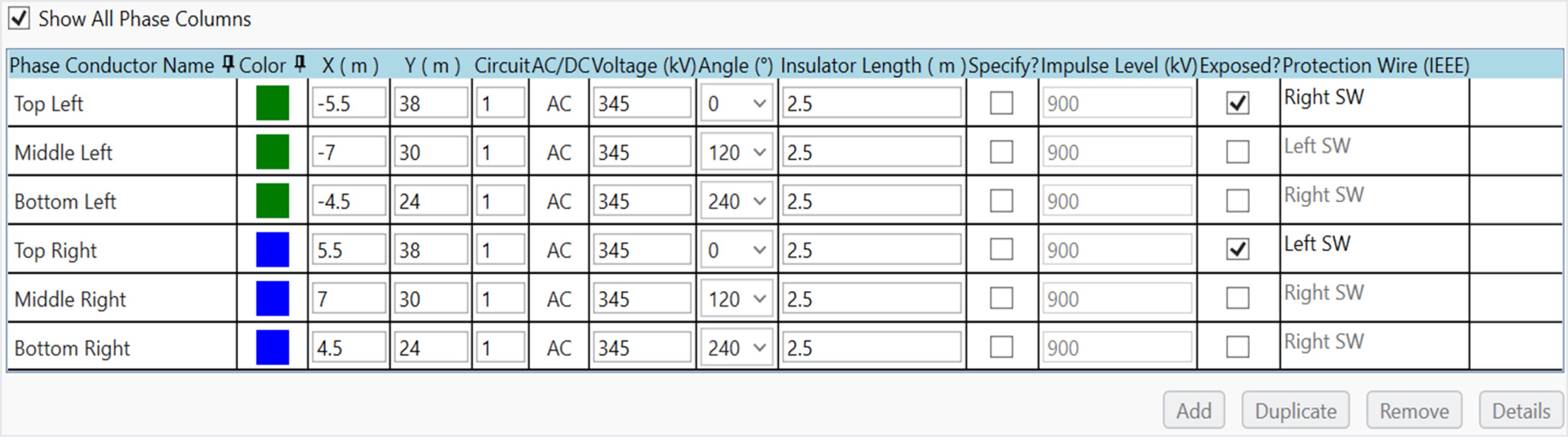
The usability of the Phase Conductor table of the Transmission Line Module was also enhanced, by adding a Duplicate button and a Circuit column, making it like what was shown in SESShield Legacy (Figure 9).
Figure 9: SESShield-2D Phase conductor table.
Additionally, the Viewer of the vertical configurations of phase wires with conductor bundles was redesigned, ensuring an immediate understanding of the whole system (Figure 10).
Figure 10: Phase configuration viewer.
SESTransient
Several improvements and new features were implemented in SESTransient since the 2022 CDEGS Users’ Group Conference (UGC). These improvements include an automated conductor subdivision method, which adaptively selects the segment length of conductors according to the characteristics of the propagation medium and to the distance separating the conductors from the energization location. Additionally, support for HIFREQ power cable component filtering was improved, a new type of lightning surge based on the IEC-62305 standard was introduced and SESTransient is now compatible with the multi-Region soil model.
See the article entitled "Improvements in SESTransient" in the 2023 Users' Group Conference Proceedings for further details.
Frequency-dependent conductor and plate subdivision (FDCS) is implemented in SESTransient. Its usefulness in reducing users’ time and computation time is illustrated with several examples. This FDCS enhancement offers three subdivision methods in SESTransient. Method 1 is the user-defined one, as before. In Method 2, the subdivisions are computed according to specific criteria and kept the same at all frequencies (Adaptive method). Method 3 is based on computations optimized for each frequency (Full FDCS method). Relatively rare cases warrant the use of the full FDCS method and henceforth, the Adaptive method is the recommended one, as it dispenses users from specifying subdivision numbers, makes use of them, if specified, and adapts accordingly if the soil model or details of the input signal and delivery points are changed.
See the article entitled "Adaptive Subdivision in SESTransient" in the 2023 Users' Group Conference Proceedings for further details.
SESTrainSimulator
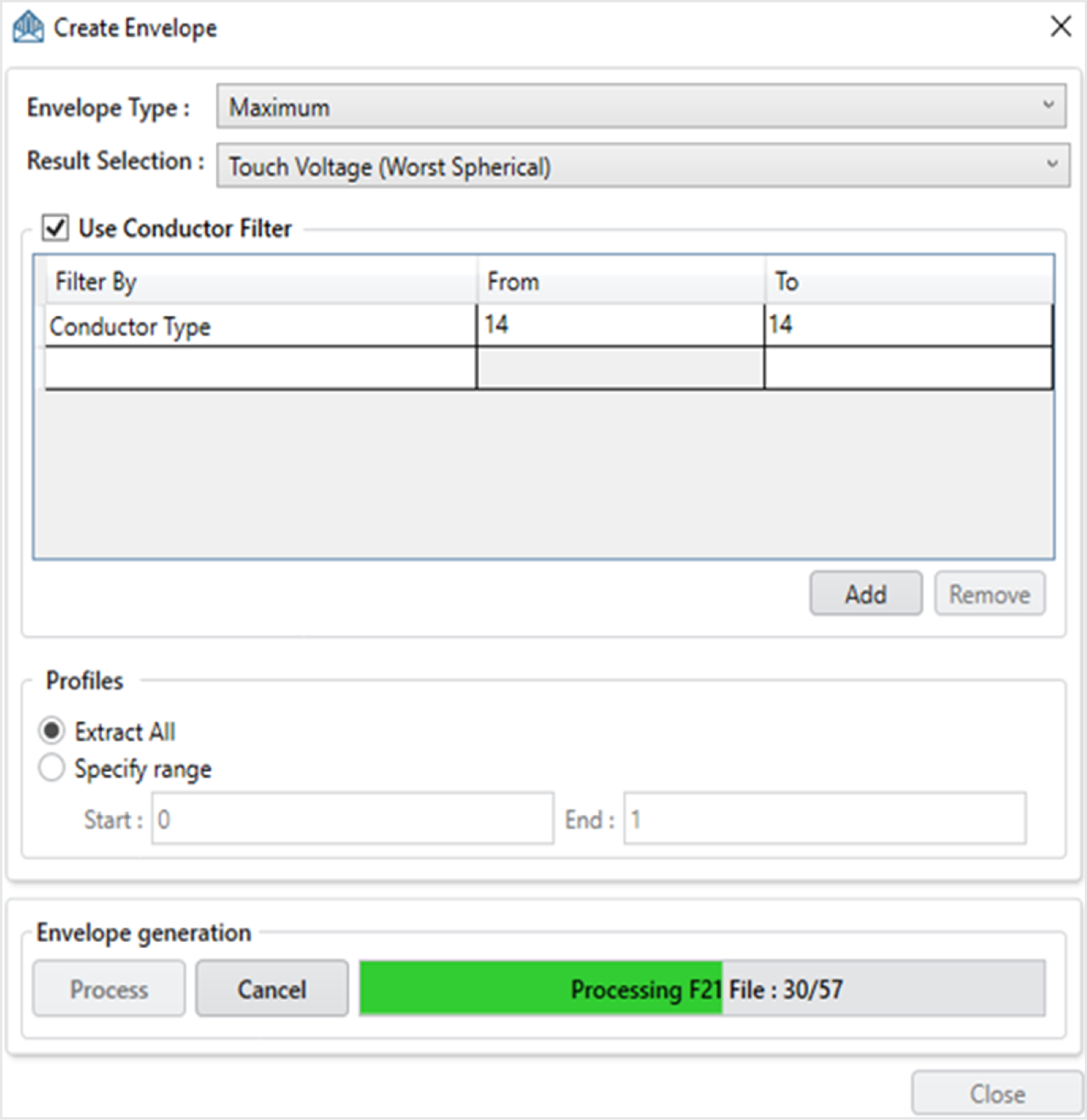
It is now possible to create envelope plots of the maximum, minimum, average and RMS results for conductor-related quantities such as current, GPR or coating stress, and many more. This is a distinct mechanism which complements the combined results feature presented last year, since the combined results could only produce envelope plots for electric and magnetic fields, and scalar and vector potentials. You can filter the results according to the conductor type, the coating type, the radius, and the original conductor number, just as you would in SESResultsViewer. You can also limit the results to a subset of the observation profiles defined in the model. The Create Envelope interface is very similar to SESResultsViewer and includes a progress bar, as shown in Figure 11.
Figure 11: The Create Envelope interface, extracting the maximum
touch voltage envelope for conductor type 14 over all defined profiles.
The train data is now accessible in the user-interface. You can edit the table manually, paste a large set of data copied from elsewhere, or import data from a csv file. The data grid allows sorting quantities is ascending or descending order and you can reorder the columns to facilitate your pasting operations.
See the article entitled "New Features and Improvements in SESTrainSimulator" in the 2023 Users' Group Conference Proceedings for further details.
|