Acceleration of Current Distribution Calculation in MALZ Without Parallel Computing
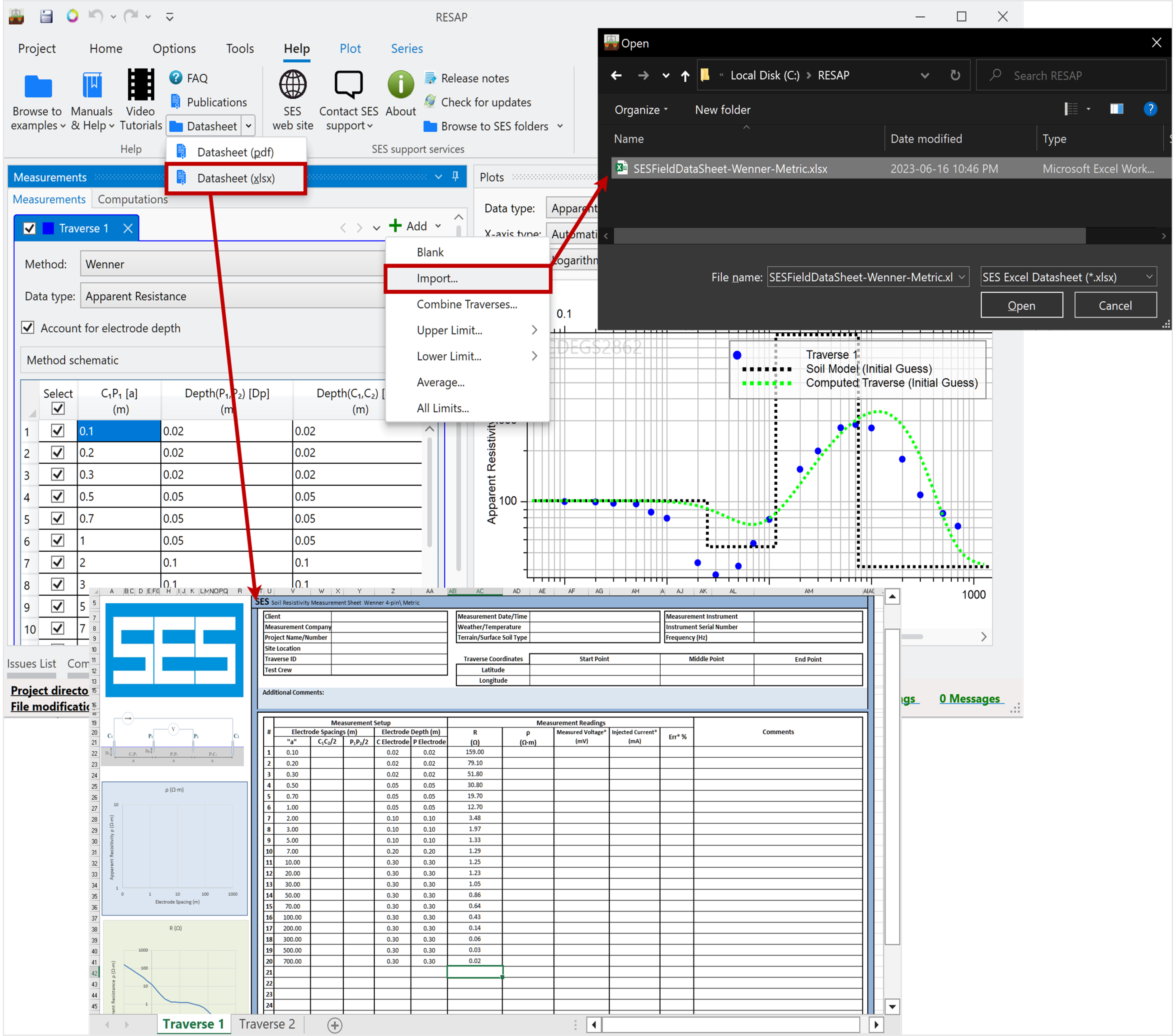
There have been several substantial reductions in the time needed to calculate the current distribution in a MALZ conductor network, especially noticeable for cases that include many conductors, with or without finite volumes. A reduction of the computation time by a factor of four for cases with 5,000 conductors and ten for 15,000 conductors was achieved. Speed improvements for cases with finite volumes are also very noticeable when a precomputation of the leakage current is requested, even for systems with relatively few conductors. These speed improvements are measured based on a single CPU core computation.
See the article entitled "Acceleration of Current Distribution Calculation in MALZ without Parallel Computing" in the 2023 Users' Group Conference Proceedings for further details.
Current Recovery with Finite Volumes
Current recovery, a feature available in MultiGround (MALT computation module), MultiGroundZ (MALZ computation module) and MultiFields (HIFREQ computation module), allows users to add observation points to a simulation and get the results very quickly by recovering the previously computed current distribution from a F33 file. This feature was previously disabled for models containing finite volumes in MultiGround and MultiGroundZ. It is now fully functional for any soil containing finite volumes in both packages.
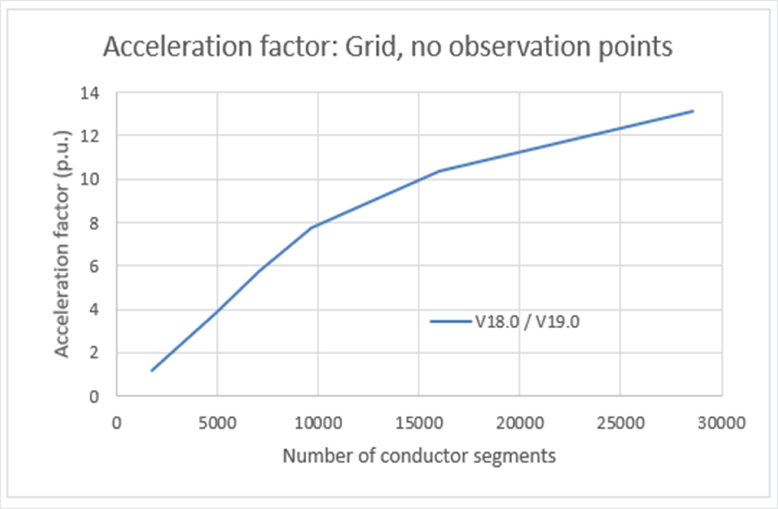
To evaluate the time savings provided by the current recovery option for cases with finite volumes, we created a model with a grounding grid buried in a two-layer soil containing two finite volumes and energized with 1,000 A at 60 Hz., as shown in Figure 2.
Figure 2: (a) 3D perspective of a grounding system consisting of a simple grid
in a two-layer soil with finite volumes. (b) Cross-section of the soil model and grid.
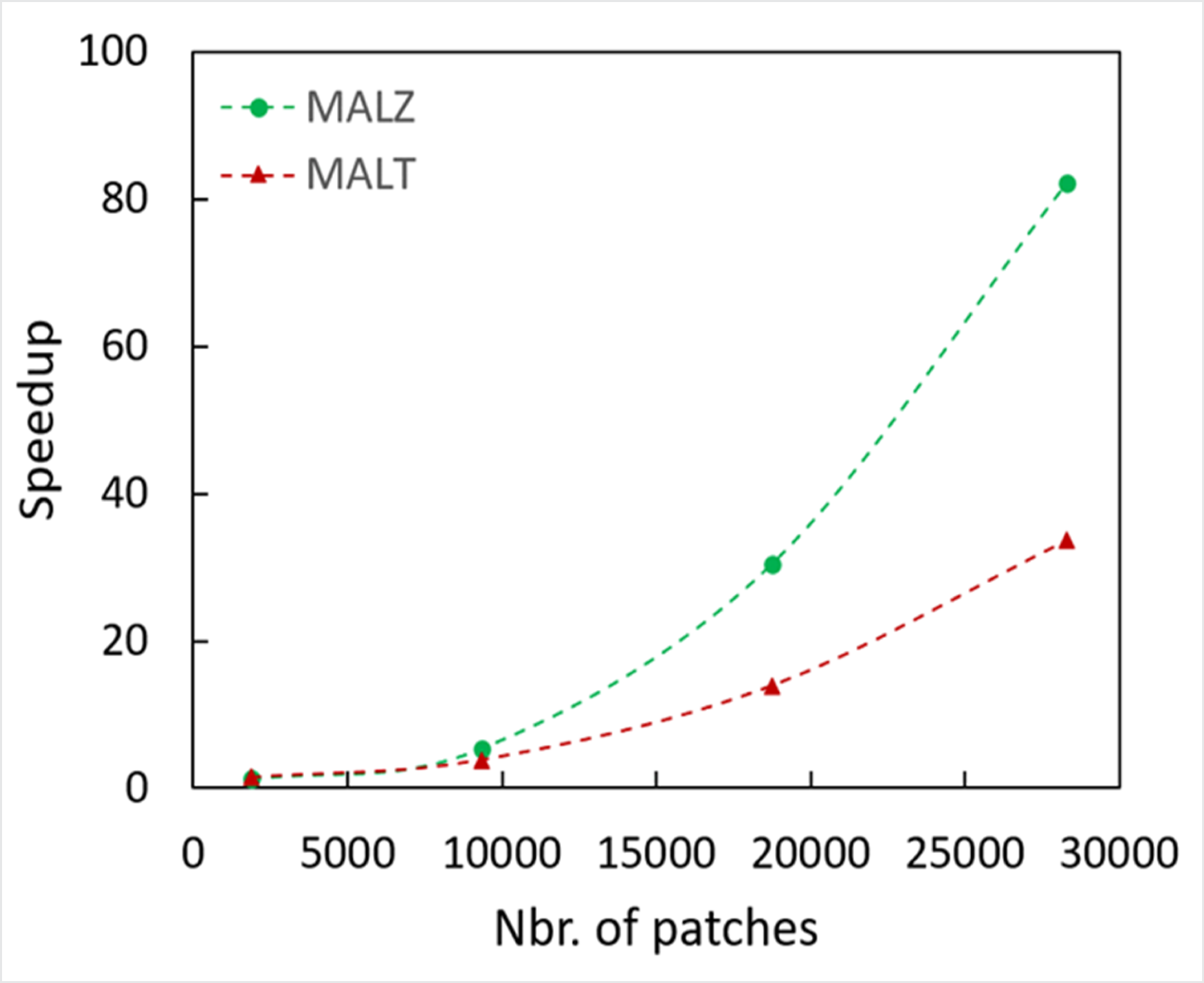
The simulation was repeated three times in both MALZ and MALT and the computation times were averaged. The speedup, defined as the time of normal run divided by the time of the recovery run, increases with the number of volume patches until it reaches above 80x and 30x, for MALZ and MALT respectively, close to the program limit of 30,000 patches, as shown in Figure 3.
Figure 3: Speedup due to current recovery in MALZ and MALT.
See the article entitled "Current Recovery with Finite Volumes" in the 2023 Users' Group Conference Proceedings for further details.
Regular, EMF and Working Potential Energizations in MALZ
MALZ can now run when unassigned energizations are defined, freeing users from the obligation of deleting all unused energizations prior to running the case. In addition, the program can now run when only EMF or working potentials are defined, but with no energization buses defined, thereby liberating users from having to define placeholder energizations only for the purpose of getting the program to run. See the article entitled "Unused Energization Buses and Energization by EMF and Working Potentials in MALZ" in the 2023 Users' Group Conference Proceedings for further details.
Acceleration of Current Distribution Calculation in HIFREQ – Phase II
The time needed to calculate the current distribution in HIFREQ models with many elements (conductor segments or plate patches) has been substantially reduced. A reduction by a factor of four or greater is possible in cases having 2,000 elements or more. The reduction can reach a factor of ten for cases including 7,000 elements or more.
See the article entitled “Acceleration of Current Distribution Calculation in HIFREQ – Phase II” in the 2023 Users' Group Conference Proceedings for further details.
In the upcoming 19.0 version, SESFcdist will be seamlessly integrated into SESCircuitSimulator, resulting in a unified visual environment for fault current distribution analysis. With the ongoing revamp of SESFcdist, the data presentation and specifications in the new interface will promote a more intuitive and user-friendly workflow.
It is possible to load an SESFcdist input file (FC_*.F05) and view the Central Site and Terminals data. Furthermore, the following Block configurations of SESFcdist data can be loaded and viewed in SESCircuitSimulator:
- Distribution Line with One Neutral.
- Overhead Transmission Line with One Shield Wire.
- Overhead Transmission Line with Two Identical Shield Wires.
- Multiple Circular Bundles (e.g., Two Different Shield Wires).
- Impedance Method.